Intro
In this post I want to show how I’ve built an AI agent which is able to troubleshoot a network issue.
I’d like to include all implementation details; hence, anyone can reproduce it or build his own agent.
I do not claim that this is the only right approach, but it is my way…
The use case
The use case is very simple: I want an AI agent that can find an artificially injected error in a working Cisco lab. In practice, that means I break one thing, and the agent has to reason its way back to the root cause by gathering evidence from the network.
My technology stack for this project
- Codex (OpenAI) running as a VS Code extension
- My own python MCP server running on my laptop as an HTTP service
- Remote MPLS lab routers reachable over SSH
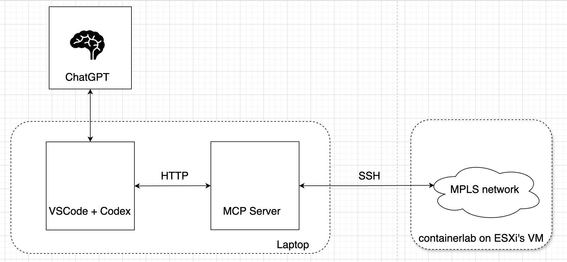
Why Codex?
The simple reason is that I use ChatGPT and Codex by default through my company account (ChatGPT Business) and I do not have any other ‘credit-card’/’token-based’ accounts.
Last time I used a local LLM, but it was just a toy. If I want to troubleshoot a more complex network, I need something advanced.
And why VSCode? Because I love it;)
MCP server
Why an MCP server? This is an important point. I discovered that Codex, when used as a VS Code extension, can connect to routers directly without any MCP server. So why MCP at all?
With an MCP server, I can define exactly what the agent is allowed to do. In my case, I restricted it to three non-configuring operations: listing routers and running commands that start with show or ping. That is a much safer and more predictable model than giving the agent unrestricted access to network devices.
It is not the same as writing down some instructions in a .md file about what an LLM is allowed to do and what it is not. It is an enforced gateway, like PAM or a proxy, within the limits of the validation rules implemented in the server. The LLM does not have any direct access to the network.
It is similar to giving a junior administrator a restricted shell account instead of full root access with instructions.
LAB environment
Now I’d like to introduce my LAB setup, but you can imagine any network or technology - it is not so important.
So, in my case, it is a small MPLS network running in Containerlab, based on Cisco IOS XR routers. The lab is intentionally simple, but it includes the core building blocks of an MPLS L3VPN service: OSPF in the provider underlay, MP-BGP VPNv4 exchange, VRFs, route distinguishers, route targets, and a route reflector. The idea was to introduce one configuration mistake into a working lab and let the agent find it.
The lab configuration is available on GitHub, and I also described the setup in my previous post.
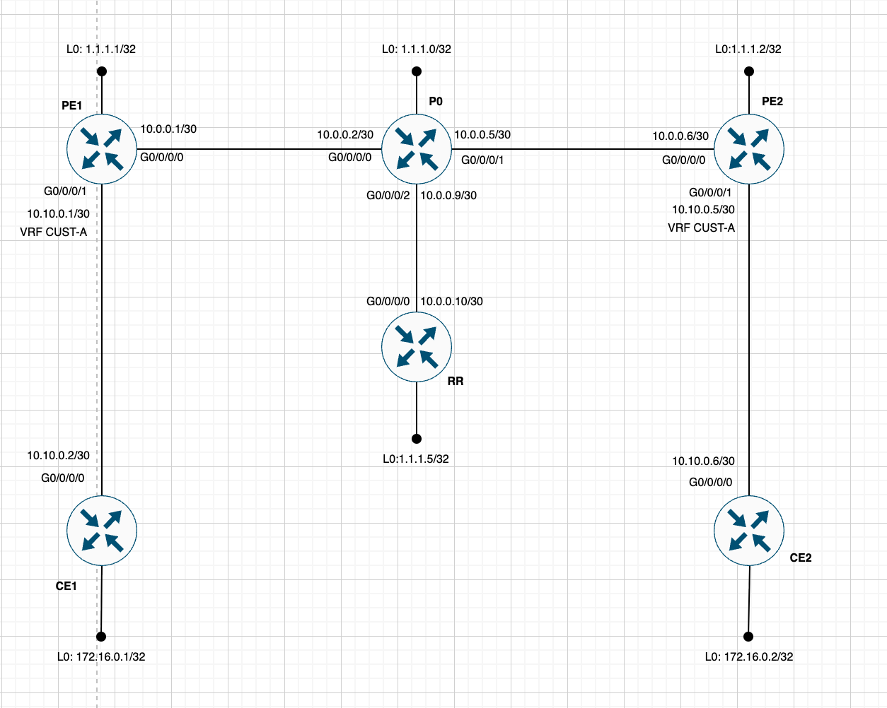
All routers are accessible over SSH from my laptop.
L3VPN over MPLS works, and I can test it by successfully pinging from the Loopback of CE1 to the Loopback of CE2:
RP/0/RP0/CPU0:CE1#ping 172.16.0.2 source 172.16.0.1
Fri Jul 17 18:39:00.853 UTC
Type escape sequence to abort.
Sending 5, 100-byte ICMP Echos to 172.16.0.2 timeout is 2 seconds:
!!!!!
Success rate is 100 percent (5/5), round-trip min/avg/max = 4/4/6 ms
Building the MCP server
My small python MCP server is based on the FastMCP library. Its job is simple: connect to the routers, run non-configuring show and ping commands, and return the results to the LLM.
It exposes three MCP tools. One lists the available routers, while the other two execute commands starting with show and ping.
Requirements and prerequisites
To reproduce this setup, you need:
- Python 3.10 or newer
- a Cisco lab that is running and reachable over SSH
- a user account that can run the required
showandpingcommands on the routers - the Codex extension installed and signed in to VSCode
- local TCP port
8000available for the MCP server
First, clone my MPLS troubleshooting agent repository and create a Python virtual environment. These commands are for macOS or Linux:
git clone https://github.com/sbezo/MPLS_troubleshooting_agent_2026.git
cd MPLS_troubleshooting_agent_2026
python3 -m venv .venv
source .venv/bin/activate
python -m pip install -r requirements.txt
The requirements.txt file installs the MCP SDK, Netmiko and python-dotenv:
mcp>=1.28,<2
netmiko>=4.7,<5
python-dotenv>=1.2,<2
Next, update nodes.json with the SSH address and port of every router. Then create a .env file in the repository directory with your credentials:
CISCO_USERNAME=your_username
CISCO_PASSWORD=your_password
If your devices require an enable secret, you can also add:
CISCO_ENABLE=your_enable_secret
The server loads this .env file automatically. It should not be committed to the repository because it contains credentials.
Let’s take a closer look at the code…
At startup, the code reads nodes.json once to verify that the inventory can be loaded and then runs an HTTP MCP server, which waits for requests. The returned dictionary is not stored at startup; the tools load the current inventory again when they need it.
if __name__ == "__main__":
    load_routers()
    try:
        mcp.run(transport="streamable-http")
    except (KeyboardInterrupt, asyncio.CancelledError):
        pass
With the virtual environment activated, start the MCP server from the repository directory:
python server.py
By default, it listens at http://127.0.0.1:8000/mcp. Keep this terminal running while using the Python client or Codex.
As the routers run in containerlab, they are accessible on the same IP address under different ports. Information about the routers is organized in a json file for simple loading into a python dictionary.
nodes.json:
{
  "P0": {"host": "10.208.116.71", "port": 2310},
  "PE1": {"host": "10.208.116.71", "port": 2311},
  "PE2": {"host": "10.208.116.71", "port": 2312},
  "CE1": {"host": "10.208.116.71", "port": 2313},
  "CE2": {"host": "10.208.116.71", "port": 2314},
  "RR": {"host": "10.208.116.71", "port": 2315},
  "CE3": {"host": "10.208.116.71", "port": 2316}
}
The function load_routers reads that json file and returns a new dictionary with router hostnames as keys and information about the connections as values. For information about the routers, I’ve created a special immutable class, Router:
@dataclass(frozen=True)
class Router:
    name: str
    host: str
    port: int


def load_routers() -> dict[str, Router]:
    """Load routers from the JSON inventory in nodes.json."""
    with DEFAULT_NODES_FILE.open(encoding="utf-8") as inventory:
        nodes = json.load(inventory)

    routers: dict[str, Router] = {}
    for name, connection in nodes.items():
        router = Router(
            name=name,
            host=connection["host"],
            port=connection["port"],
        )
        routers[name.casefold()] = router
    return routers
The first of the three MCP tools exposed to clients is list_cisco_routers:
@mcp.tool(
    name="list_cisco_routers",
    title="List Cisco Routers",
    description="List the router names available in the Cisco lab inventory.",
)
def list_cisco_routers() -> list[str]:
    return [router.name for router in load_routers().values()]
So if an MCP client (Codex in my case) asks to list routers, it gets a list of router hostnames.
Now take a look at the next tool provided by the MCP server: cisco_show_command.
It is implemented with the mcp.tool decorator again:
@mcp.tool(
    name="cisco_show_command",
    title="Run Cisco Show Command",
    description=(
        "Run one guarded, single-line Cisco CLI command beginning with 'show' "
        "on a named lab router. Examples: 'show clock', 'show interfaces brief', "
        "or 'show route'."
    ),
)
def cisco_show_command(router: str, command: str) -> str:
    return run_cisco_command(router, validate_show_command(command))
So an MCP client can ask for any command starting with the keyword show in the form of (router: str, command: str).
And the essential thing here is validation. The function validate_show_command performs a simple regexp-based prefix validation - the command passed by the client (it can be an LLM such as Codex or a deterministic python client, as we will see later) should satisfy these conditions:
- cannot be an empty string
- cannot contain non-printable control characters such as newlines or tabs
- must start with
showfollowed by whitespace
def validate_show_command(command: str) -> str:
    """Return a normalized, printable, single-line show command."""
    normalized = command.strip()
    if not normalized:
        raise ValueError("Command cannot be empty")
    if not normalized.isprintable():
        raise ValueError("Command must not contain non-printable characters")
    if not re.match(r"^show(?:\s)", normalized, flags=re.IGNORECASE):
        raise ValueError("Only commands beginning with 'show' are allowed")
    return normalized
This validation creates a real enforcement point, but it is intentionally simple. It verifies the command format and prefix; it does not compare every possible show command with an explicit allowlist. The safety of the gateway therefore depends on the validation rules implemented for each exposed tool.
After validation by validate_show_command, the command is passed to the function run_cisco_command, which invokes the Netmiko library in order to connect to the requested router and perform the requested show command:
def run_cisco_command(router_name: str, command: str) -> str:
    router = get_router(router_name)
    username, password = get_credentials()
    enable_secret = os.getenv("CISCO_ENABLE")
    device: dict[str, object] = {
        "device_type": "cisco_ios",
        "host": router.host,
        "port": router.port,
        "username": username,
        "password": password,
        "secret": enable_secret,
        "conn_timeout": 10,
    }

    try:
        with ConnectHandler(**device) as connection:
            if enable_secret:
                connection.enable()
            output = connection.send_command(
                command,
            )
    except Exception as exc:
        raise RuntimeError(
            f"SSH command failed on {router.name} ({router.host}:{router.port}): {exc}"
        ) from exc
    return output.strip()
run_cisco_command is my wrapper around Netmiko. It first calls these two helper functions:
get_router(router_name)to get complete connection information based on the provided hostname in the form of aRouterclass objectget_credentials()to get connection credentials from environment variables
def get_router(name: str) -> Router:
    routers = load_routers()
    router = routers.get(name.strip().casefold())
    if router is None:
        available = ", ".join(item.name for item in routers.values())
        raise ValueError(f"Unknown router {name!r}. Available routers: {available}")
    return router

def get_credentials() -> tuple[str, str]:
    username = os.getenv("CISCO_USERNAME")
    password = os.getenv("CISCO_PASSWORD")
    if not username or not password:
        raise RuntimeError(
            "Missing credentials. Set CISCO_USERNAME and CISCO_PASSWORD in .env."
        )
    return username, password
After the helper functions return, run_cisco_command builds the device dictionary. Netmiko’s ConnectHandler opens the SSH connection, and send_command executes the requested command. The wrapper strips the output and returns it to the MCP client.
And that is the whole concept of the MCP server. The ping tool uses the same pattern with its own validator. The MCP server can be extended with additional command families by adding a dedicated validator and MCP tool for each one.
To firmly grasp this mental model, I’ve prepared a small deterministic Python MCP client. This minimal client specifically calls the cisco_show_command tool. And I think this is a real cornerstone of the whole MCP concept.
You can utilize the MCP server with this client without any LLM miracle. With the server running, open another terminal, activate the same virtual environment and run:
source .venv/bin/activate
python client_simple.py --router PE1 --command "show clock"
Sun Jul 19 06:30:58.911 UTC
06:30:58.932 UTC Sun Jul 19 2026
Or:
python client_simple.py --router CE2 --command "show ip route"
Sun Jul 19 06:33:15.330 UTC

Codes: C - connected, S - static, R - RIP, B - BGP, (>) - Diversion path
       D - EIGRP, EX - EIGRP external, O - OSPF, IA - OSPF inter area
       N1 - OSPF NSSA external type 1, N2 - OSPF NSSA external type 2
       E1 - OSPF external type 1, E2 - OSPF external type 2, E - EGP
       i - ISIS, L1 - IS-IS level-1, L2 - IS-IS level-2
       ia - IS-IS inter area, su - IS-IS summary null, * - candidate default
       U - per-user static route, o - ODR, L - local, G  - DAGR, l - LISP
       A - access/subscriber, a - Application route
       M - mobile route, r - RPL, t - Traffic Engineering, (!) - FRR Backup path
       s - local SRv6 route, z - local IID route

Gateway of last resort is not set

C    10.10.0.4/30 is directly connected, 2w4d, GigabitEthernet0/0/0/0
L    10.10.0.6/32 is directly connected, 2w4d, GigabitEthernet0/0/0/0
S    172.16.0.1/32 [1/0] via 10.10.0.5, 2w4d
L    172.16.0.2/32 is directly connected, 2w4d, Loopback0
C    192.168.200.0/24 is directly connected, 2w4d, GigabitEthernet0/0/0/1.200
L    192.168.200.2/32 is directly connected, 2w4d, GigabitEthernet0/0/0/1.200
C    192.168.230.0/24 is directly connected, 2w4d, GigabitEthernet0/0/0/1.300
L    192.168.230.2/32 is directly connected, 2w4d, GigabitEthernet0/0/0/1.300
(.venv) stefanbezo@Stefans-MacBook-Pro MPLS_troubleshooting_agent_2026 %
This was quite a long excursion into the MCP code, but I think that it was important for those who really want to understand this concept.
The next step is registering the MCP server with VSCode.
Registering the MCP server with Codex
This is a very simple step, but also an important one - It interconnects Codex powered by ChatGPT with the new MCP server.
Open ~/.codex/config.toml and add these two lines:
[mcp_servers.cisco-lab]
url = "http://127.0.0.1:8000/mcp"
Then press Shift + CMD + P and run Developer: Reload Window to reload the current VSCode window.
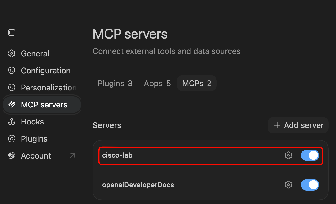
After that, the new MCP server should appear in the Codex plugin settings in VSCode. If it does not appear, first confirm that python server.py is still running and that http://127.0.0.1:8000/mcp matches the configured server address:
Testing LAB reachability by Codex
As I already tested the MCP server itself with my Python MCP client, the next step is to check if Codex can also reach my LAB through the MCP server.
So let’s try a canary test…
First I created a fresh new project so as not to influence Codex in any way and asked it to:
- Connect to cisco-lab MCP server
- Check configurations
- You do not need to diagnose anything yet
- Tell me a short conclusion about the network
And this was Codex’s answer:
The seven-router lab is configured as a coherent MPLS provider network:
OSPF + LDP core with P0, PE1, PE2, and RR.
VPNv4 iBGP through the route reflector.
CUST-A L3VPN connects CE1 and CE2.
VLAN 200 uses a point-to-point L2VPN; VLAN 300 uses a multipoint bridge/VPLS service including CE3.
Overall, the configurations are structurally consistent. This was configuration review only—not a live-health diagnosis.
Perfect, it is able to use MCP and it understands the router configurations.
So it is time to prepare an exam for Codex:)
And it’s exam time
Now everything is ready to test Codex’s ability to troubleshoot an MPLS network.
I let Codex work in the repo with the MCP server to have all files together. And I prepared some guidelines for it:
- You are a troubleshooting expert for the Cisco IOS XR platform
- Use the running native MCP server 'cisco-lab'
- Log all commands and outputs to the session.log file
- Log all your reasoning and a short record of our communication with timestamps to the reasoning.log file
Then I started the chat:
1. Read the AGENT.md file with general instructions
2. Check connectivity to all routers via the MCP server
3. Check connectivity from CE1 to CE2 via the L3VPN MPLS network with 'ping 172.16.0.2 source 172.16.0.1'
Codex first established a healthy baseline. It reached all seven routers through the MCP server and the test ping from CE1 to CE2 returned five out of five replies:
Success rate is 100 percent (5/5), round-trip min/avg/max = 3/3/5 ms
Then I injected an artificial error into the network - I changed the IP MTU on a PE interface to break the OSPF process in the underlying MPLS network.
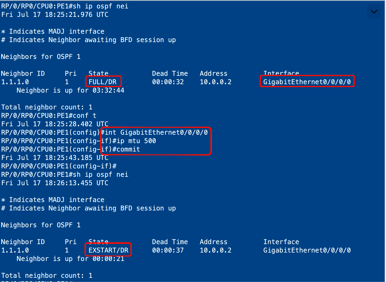
Then I continued with a challenge for Codex:
4. I injected a configuration error into one of the nodes to test your troubleshooting skills. Try to find it and propose a solution.
Codex started by reproducing the problem with the same sourced ping. This time, it received no replies:
Success rate is 0 percent (0/5)
The troubleshooting path
Codex then moved through the network layer by layer:
- It checked the routes and interfaces on CE1 and CE2 with
show routeandshow ipv4 interface brief. Both CEs had the expected static routes, and their loopback and PE-facing interfaces were up. - It pinged the directly connected PE next hops from both CEs. Both tests returned five out of five replies, ruling out the CE-to-PE access links.
- It checked
CUST-Aon PE1 and PE2 withshow vrf all. Both routers still had the expected route target65000:100. - It inspected the customer routes on both PEs. PE1 had its local
172.16.0.1/32route but was missing the remote172.16.0.2/32route. PE2 showed the opposite. This pointed to a VPNv4 route-exchange problem rather than an access-link failure. - It checked the VPNv4 BGP sessions. The PE1-to-RR session was
Idle, while the PE2-to-RR session remained established. The detailed neighbor output reportedNo route to multi-hop neighbor. - It tested connectivity between the PE1 and RR loopbacks. The pings failed in both directions, and neither router had a route to the other router’s loopback. This moved the investigation from MP-BGP to the underlay.
- It inspected OSPF on PE1, P0 and RR. The PE1-P0 adjacency was stuck in
EXSTART/EXCHANGE, while the P0-PE2 and P0-RR adjacencies remainedFULL. That localized the problem to the link between PE1 and P0 and strongly suggested an MTU mismatch.
Root cause
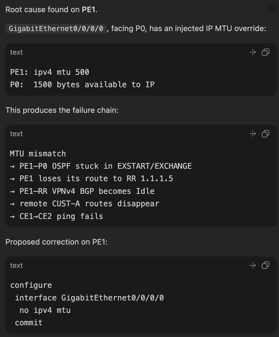
Codex compared the interface configuration on the affected PE1-P0 link with the corresponding configuration on P0 and the healthy P0-PE2 link. It found this unexpected command on PE1 GigabitEthernet0/0/0/0:
interface GigabitEthernet0/0/0/0
 ipv4 mtu 500
 ipv4 address 10.0.0.1 255.255.255.252
!
The operational interface output confirmed that PE1 had only 500 bytes available to IP, while the directly connected P0 interface had 1500 bytes available:
PE1: MTU is 1514 (500 is available to IP)
P0:  MTU is 1514 (1500 is available to IP)
This gave Codex the complete causal chain:
PE1-P0 IP MTU mismatch
    -> OSPF database exchange cannot complete
    -> PE1 loses its underlay route to the route reflector
    -> PE1-RR MP-BGP becomes Idle
    -> remote VPNv4 routes disappear
    -> the CE1-to-CE2 L3VPN ping fails
Codex proposed removing the injected ipv4 mtu 500 override from PE1 GigabitEthernet0/0/0/0, allowing the interface to return to the 1500-byte IP MTU used by P0. It also explicitly advised against using OSPF MTU-ignore as the primary correction because that would leave the underlying data-plane MTU mismatch in place.
Time and validation
According to the timestamps in the logs, I submitted the troubleshooting challenge at 20:28:11. Codex confirmed the MTU mismatch and completed its diagnosis at 20:36:39, approximately eight and a half minutes later.
The MCP server intentionally provided only non-configuring show and ping operations, so Codex could not apply the change. Instead, it proposed the following validation plan after the correction:
- confirm that the PE1 IP MTU has returned to 1500 bytes
- confirm that the PE1-P0 OSPF adjacency reaches
FULL - confirm that the reciprocal PE1 and RR loopback routes return
- confirm that the PE1-RR VPNv4 BGP session becomes established
- confirm that both remote
CUST-Aroutes are installed - repeat the original sourced ping from CE1 to CE2
The session log contains every command and its output. The separate reasoning log records how each result determined the next diagnostic step.
So, Codex found the root cause, explained the complete failure chain, suggested the correct solution and passed my exam:)
Conclusion
This was a bit of a long post, but I wanted to explain all the technical details for those who would like to build something similar.
It can be another network, a Kubernetes cluster or a Firewall - the concept stays the same, and only the MCP server should be slightly changed.
Happy building…;)